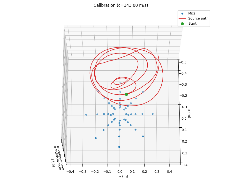
 Output from moving white noise sound source in a spiral pattern.
 Overview
The project implements a low-cost complete acoustic imaging pipeline using a 48‑channel acoustic phased array (heavily inspired by Ben Wang's project):
- 48 microphones arranged radially on a custom PCB, generating 1‑bit PDM streams.
- FPGA clocks and samples PDM, packs data, and streams via UDP using LiteEth.
- Host capture taps raw Ethernet via macOS /dev/bpf and writes into a shared memory ring.
- CIC decimation converts 1‑bit PDM to multi‑channel PCM int32.
- GCC‑PHAT in the frequency domain retrieves robust TDOAs per frame.
- Nonlinear optimization (PyTorch) recovers mic positions, source trajectory, and speed of sound.
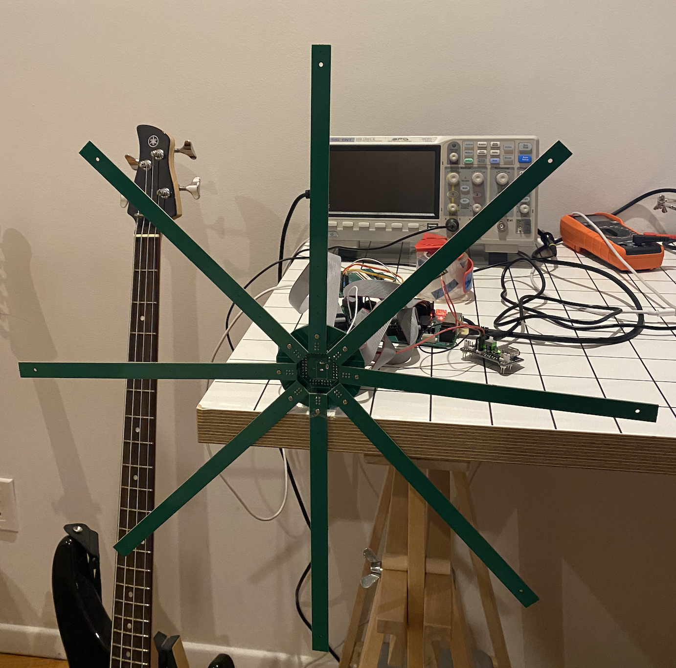 Acoustic phased array assembly
 Hardware: 48‑Mic Circular Array
The array consists of eight arms, each with three pins, and each pin carrying two microphones: inner (H) and outer (L). The full array exposes 24 stereo lines → 48 channels.
PCB/Layout
Custom spokes + hub PCBs.
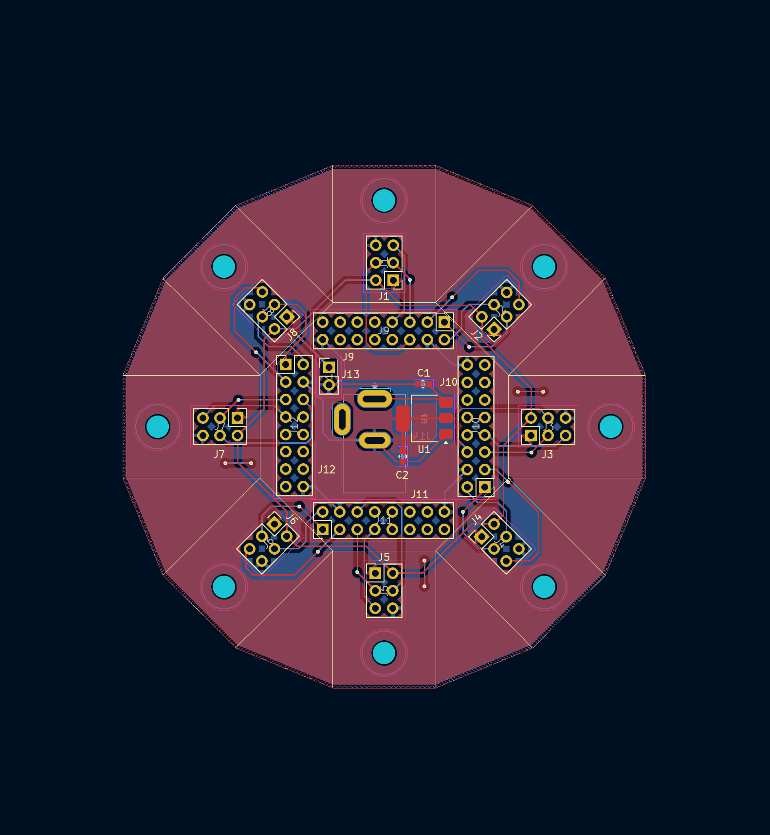 Hub
Hub 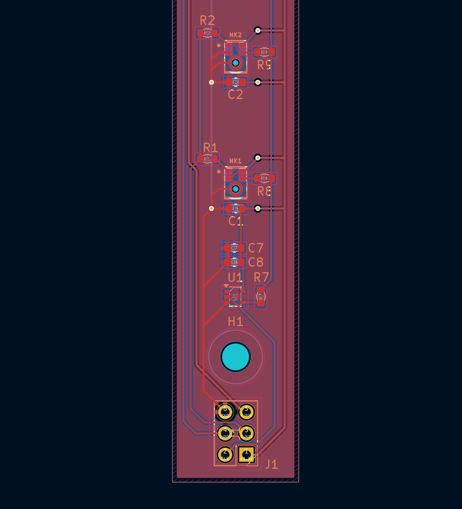 and Spoke!
 On the FPGA side, we simply leverage the pin mapping from Chubby75 of the Colorlight 5a-75B board. The hardest part here was removing the 74HC245 buffer between the FPGA and the microphones to enable 3.3V logic inputs and soldering tiny flex PCBs (this took a lot of trial and error to do consistently).
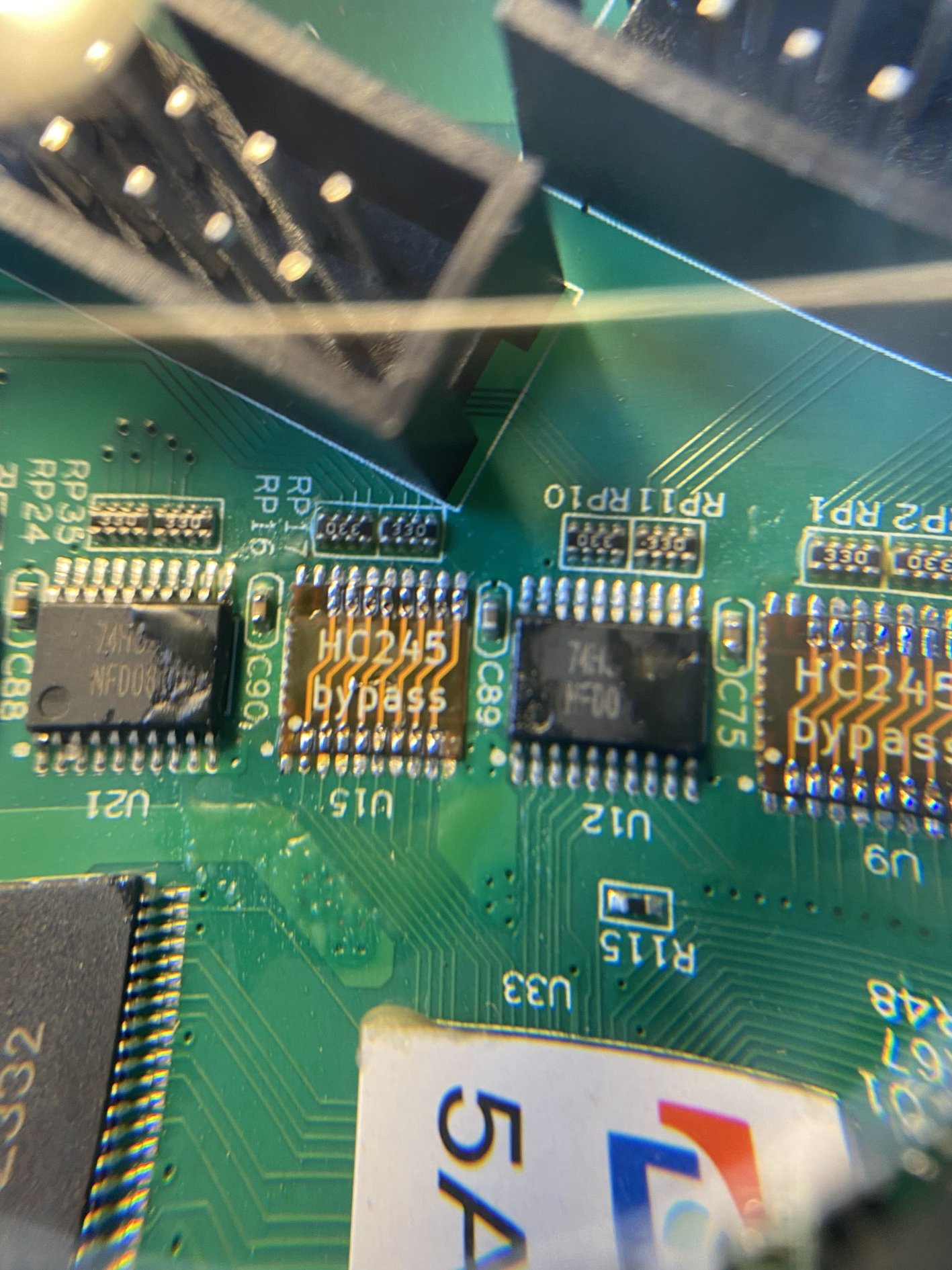 so tiny D:
 FPGA: PDM Sampling → UDP Payloads
On‑FPGA logic clocks the shared PDM data line per pin, sampling on both edges to separate inner/outer microphones. Words are emitted in 12‑byte groups: [packet_id, word_prev, word_curr], repeated to fill UDP payloads.
# fpga/pdm.py — PDM capture into a 32-bit stream
class PDM(Module):
    def __init__(self, clk_pad, data):
        self.clk_pad = clk_pad
        self.source = stream.Endpoint([("data", 32)])
        count = Signal(4)      # 0..15 (rising/falling edges)
        packet_id = Signal(32)
        data_reg = Signal(24)

        # Capture around edge; emit packet_id then data words
        self.sync += If((count & 7) == 5, data_reg.eq(data))
        self.comb += self.clk_pad.eq(count[-1])  # drive PDM clock

        stmt = If((count & 15) == 0,
                  self.source.data.eq(packet_id),
                  self.source.valid.eq(1),
                  self.source.first.eq(1))
        stmt = stmt.Elif((count & 7) == 1,
                         self.source.data.eq(data_reg),
                         self.source.valid.eq(1),
                         self.source.first.eq(0))
        self.sync += stmt.Else(self.source.valid.eq(0), self.source.first.eq(0))
        self.sync += If((count & 15) == 9, self.source.last.eq(1)).Else(self.source.last.eq(0))
        self.sync += [count.eq(count + 1), If((count & 15) == 15, packet_id.eq(packet_id + 1))]
The UDP path is built on
LiteEth. See
fpga/main.py for SoC instantiation and port wiring.
Host Capture: macOS BPF → Shared Ring
On the host, a zero‑copy capture tool uses /dev/bpf to parse VLAN + IPv4 + UDP, extract the packed 12‑byte groups, and write interleaved PCM batches into a memory‑mapped ring file for Python to consume.
// beamforming/fastcap_pcm.c — ring header and write helper
struct ring_header {
    char magic[8];
    uint32_t version; uint32_t reserved0; uint64_t capacity_bytes;
    _Atomic uint64_t write_pos, read_pos, dropped_by_bpf, blocked_waits;
    uint32_t linktype; uint32_t reserved1;  // LINKTYPE_PCM
};

static void ring_write_pcm_multi(struct ring_header *hdr, uint8_t *data,
    const int32_t *interleaved, size_t frames, size_t channels,
    uint32_t ts_sec, uint32_t ts_usec) {
    // ... writes one aligned record with a small header + payload ...
}
// IPv4/VLAN/UDP parsing → unpack 3x32-bit groups and feed CIC
if (parse_udp_payload_ipv4_vlan(pkt, caplen, &udp, &udp_len, udp_port)) {
size_t num_words = udp_len / 4;
if (num_words >= 3) {
const uint8_t *wp = udp; size_t frames = num_words / 3;
for (size_t i = 0; i < frames; i++) {
uint32_t w_prev = *(uint32_t*)(wp + 4);
uint32_t w_curr = *(uint32_t*)(wp + 8);
// run CIC per line, interleave L/H; batch and commit to ring
// ...
wp += 12;
}
}
}
Default ring path is /tmp/fastcap_pcm.ring, with
linktype set to 0xFFFF to denote PCM.
CIC Decimation: 1‑bit PDM → Multichannel PCM
Each line carries two PDM streams (outer/inner) captured on alternate edges. A parameterizable CIC (Cascaded Integrator‑Comb) converts the 1‑bit streams into wide dynamic‑range PCM.
// beamforming/fastcap_pcm.c — 3‑stage CIC with decimation R (default 64)
typedef struct { int stages, R, decim_count; int64_t intL[8], intR[8], combL[8], combR[8]; } CIC;
static bool cic_process_bit(CIC *c, uint32_t bitL, uint32_t bitR, int32_t *outL, int32_t *outH) {
    int64_t vL = cic_integrate(bitL ? 1 : -1, c->intL, c->stages);
    int64_t vR = cic_integrate(bitR ? 1 : -1, c->intR, c->stages);
    if (++c->decim_count < c->R) return false; c->decim_count = 0;
    int64_t yL = cic_comb(vL, c->combL, c->stages);
    int64_t yR = cic_comb(vR, c->combR, c->stages);
    return true;
}
With a PDM clock of ≈3.125 MHz and decimation R=64,
the PCM rate is ≈48.828 kHz. The decimator runs per line,
emitting frames interleaved as L1,H1,L2,H2,…,L24,H24.
Python Ingest: Ring → WAVs
Python readers consume the ring and write WAVs.
Time‑Difference Estimation: GCC‑PHAT
Frames are windowed and transformed. Generalized cross‑correlation with PHAT weighting produces robust TDOA estimates relative to a handful of reference microphones.
# beamforming/calibration.py — GCC‑PHAT core
def gcc_phat_tdoa(frames, sample_rate, ref_indices, max_lag_s=0.004):
    T, N, C = frames.shape
    nfft = 1 << (N - 1).bit_length()
    X = np.fft.rfft(frames, n=nfft, axis=1)           # (T,F,C)
    tdoa = np.zeros((T, len(ref_indices), C), np.float32)
    peak = np.zeros_like(tdoa)
    eps = 1e-12
    for ri, ref in enumerate(ref_indices):
        Xr = X[:, :, ref]
        Rxc = Xr.conj()[:, None, :] * X.transpose(0, 2, 1)
        Rxc /= (np.abs(Rxc) + eps)                     # PHAT
        corr = np.fft.irfft(Rxc, n=nfft, axis=2)
        # fftshift + local window; take argmax for TDOA per channel
        # ...
    return tdoa, peak
Nonlinear Optimization: Mic Geometry, Source Path, Speed of Sound
We jointly optimize microphone positions (48×3), a 3D source trajectory over frames, and the speed of sound. The loss penalizes TDOA residuals with a Huber term (reduces impact of outliers), while regularizing mic positions near the design, enforcing planar mics, and smoothing the trajectory.
# beamforming/calibration.py — loss sketch
def loss_fn(mic_pos, src_pos, log_c, tdoa, mask, ref_indices):
    c = torch.exp(log_c)
    d = torch.linalg.norm(src_pos[:, None, :] - mic_pos[None, :, :], dim=2)
    d_ref = d[:, ref_indices]
    pred = (d[:, None, :] - d_ref[:, :, None]) / c
    valid = mask.clone();
    for ri, ref in enumerate(ref_indices):
        valid[:, ri, ref] = False
    diff = torch.where(valid, pred - tdoa, torch.zeros_like(pred))
    absd = torch.abs(diff); delta = 2e-4
    huber = torch.where(absd <= delta, 0.5*(absd**2)/delta, absd - 0.5*delta)
    data = huber.sum() / valid.sum().clamp(min=1)
    reg = 5e-3*((mic_pos - mic0)**2).mean() + 2e-3*(mic_pos[:,2]**2).mean()
    return data + reg + 1e-2*jerk_reg(src_pos) + 5e-3*accel_reg(src_pos) + 1e-5*((c-343.0)**2)
Next Steps
The project is a work in progress and there are many things that can be improved.
- Build a more rigid assembly + FPGA housing to avoid having to recalibrate.
- Move CIC decimation to FPGA and push the limits of number of channels we can handle on standard Gigabit Ethernet.
- Adjust TDOA calculation to be pairwise instead of relative to a reference microphone.